Modules:
SAMS (Symbolic Analyses of Mechanical Systems)
SAMS / Suspension kinematics
SAMS / Vehicle steady states
Models created in the Matab/Simulink+Simmechanics environment
Data Analysis
Trajectory
SADT (System of Automotive Development Tools) is used to support the mechanical design of a vehicle, analysis of dynamic states (calculated and measured) and optimize kinematic and dynamic characteristics of wheel suspensions as well as vehicle subsystems that affect driving characteristics of a car.
This is an interactive and open system that interconnects individual tools (both our own and commercial). Matlab software is used as an integrating environment.
Key characteristics:
-
The system is hierarchical and includes models of various levels, from the simplest models to the complex models that are connected with the input data. Complex models use parameter values from simpler models to obtain data for more complex structures. On the contrary, the simple models use data from complex models.
-
Individual models and sub-models are used in various stages of vehicle development and with various types of tools (e.g. both in simulation tools and data analysis tools).
-
Output quantities
-
ISO 8855 and SAE J670e
-
Special outputs: combination of data measured and calculated based on the vehicle models or its subsystems
-
Tools supporting “rational setup”
Individual elements of the systems:
SAMS (Symbolic Analyses of Mechanical Systems)
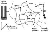 Multi-body software SAMS is used to create mathematical models of general mechanical systems. Based on the topology of the mechanicals system, the program generates equations for the given type of tasks using the syntax of C, C++ programming language. General part of the program is equally extended for the use of vehicle dynamics. Multi-body software SAMS is used to create mathematical models of general mechanical systems. Based on the topology of the mechanicals system, the program generates equations for the given type of tasks using the syntax of C, C++ programming language. General part of the program is equally extended for the use of vehicle dynamics.
This software represents one of the basic elements of the SADT system, as it is the core of other system modules. It quickly generates equations to solve many special tasks such as driving characteristics of a vehicle, from wheel suspension kinematics to the complete dynamics of a car. The software generates equations also for tasks that combine direct and inverse problems. Considering the general basis of the system, it can also be easily used outside the field of vehicle dynamics.
Author of the software: Ing. Petr Porteš, Ph.D.
Characteristics
SAMS / Suspension kinematics
The program optimizes kinematic properties of axles and can be used for development of new suspension and optimization of existing axle by means of adjustments available on the axle (washers, changing positions of ball joints, position of flange, etc.). Parameters obtained from this module are used as input parameters for other SADT modules.
Mathematical description of axles is created by SAMS that generates equations for any type of suspension. Therefore the choice is not limited to few predefined types of suspension, as is typical for other programs. Since the equations are generated, their structure can be adapted to available input data.
 The software calculates all useful kinematic characteristics of suspensions. The axle model including the wheel springing mechanism (e.g. push-rod, mechanism of stabilizer) also provide all important transfers of forces, moments and ride/roll rates from springs and anti-roll bars to wheel center or road-wheel contact rates (e.g. „wheel vertical force / spring force “, „ wheel vertical force / anti-roll bar torque“, wheel suspension roll stiffness). The software calculates all useful kinematic characteristics of suspensions. The axle model including the wheel springing mechanism (e.g. push-rod, mechanism of stabilizer) also provide all important transfers of forces, moments and ride/roll rates from springs and anti-roll bars to wheel center or road-wheel contact rates (e.g. „wheel vertical force / spring force “, „ wheel vertical force / anti-roll bar torque“, wheel suspension roll stiffness).
The software has a special algorithm for optimization of axles. Individual kinematic characteristics are divided into 3 groups according to the requirements for properties that are to be obtained by the calculation. The first group comprises kinematic quantities that should have specific value in one working point (most often in basic height, e.g. toe-in, camber, track, roll center height, anti-dive etc. at the vehicle’s working height). The second group includes the dependence of kinematic characteristics on wheel movement for which the whole shape is optimized, e.g. bump-steer (steer angle in the whole range of wheel movement). The third group contains kinematic characteristics in which no specific requirements are directly required. These are calculated just to check whether they show any undesired abnormality that could spoil the results of optimization calculations.
As the optimization calculations are very fast, the program can be used also to calculate new setups of axles between individual test drives. The program supports the “rational setup”.
The software is continuously updated to include other related analyses that provide important information necessary for optimization of kinematic characteristics. We are broadening interconnectivity of this module with other SADT modules.
Author of the software: Ing. Petr Porteš, Ph.D.
Characteristics
SAMS / Vehicle steady states
This program is used to analyze steady and quasi-steady states of a vehicle. It helps develop and setup the vehicle suspension, springing and other subsystems affecting car handling such as axle and center differentials or vehicle aerodynamics. As far as the system hierarchy is concerned, this module follows up the SAMS/Suspension kinematics module. It is expected that the models and parameters of suspension generated, analyzed and optimized in the mentioned module will be utilized here. As the model of the whole vehicle is again created by the SAMS software, the structure of the modeled mechanism including any type of axels, vehicle springing mechanisms, force elements, adjustment elements etc. can be adapted to the required structure of input parameters.
 The program calculates steady states (e.g. driving on the circular track at constant speed) and quasi-steady states (driving on the circular track with acceleration or braking). It also calculates individual states for the Moment Method. Based on these calculations it is possible to understand how the car performs even to its limits (on the verge of adhesion) and how individual vehicle subsystems or various chassis setups affect the car’s performance, stability and ability to steer. At the same time, inverse problems can be solved, which makes it possible to work on tasks concerning desired changes of stiffness or spring preload and stabilizers in order to obtain required position of the vehicle’s body in relation to the road. As the intensity of aerodynamic forces in racing cars is strongly dependent on the relative position of the body and road, these calculations are very important for these category of cars. The car model includes model of differentials, which allows us to analyze the effect of locking passive or active differentials and “steering” differentials (Torque Vectoring) by prescribing requirements for shaft rotational speed or moments acting on individual differential shafts. These analyses can be performed both in cars with one drive axle and 4x4 cars with or without inter-axle differential. The program calculates steady states (e.g. driving on the circular track at constant speed) and quasi-steady states (driving on the circular track with acceleration or braking). It also calculates individual states for the Moment Method. Based on these calculations it is possible to understand how the car performs even to its limits (on the verge of adhesion) and how individual vehicle subsystems or various chassis setups affect the car’s performance, stability and ability to steer. At the same time, inverse problems can be solved, which makes it possible to work on tasks concerning desired changes of stiffness or spring preload and stabilizers in order to obtain required position of the vehicle’s body in relation to the road. As the intensity of aerodynamic forces in racing cars is strongly dependent on the relative position of the body and road, these calculations are very important for these category of cars. The car model includes model of differentials, which allows us to analyze the effect of locking passive or active differentials and “steering” differentials (Torque Vectoring) by prescribing requirements for shaft rotational speed or moments acting on individual differential shafts. These analyses can be performed both in cars with one drive axle and 4x4 cars with or without inter-axle differential.
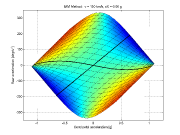
The program outputs are designed to provide the clearest understanding of the state of a car as a whole, but also the state of its individual subsystems. For instance, the state of a tyre is demonstrated in several graphs that can answer the following questions:
- To what extent the maximum potential of individual tyres is utilized? Is the tyre slip (longitudinal or lateral) lower than the value corresponding with the maximum force (longitudinal or lateral) or, is it higher?
- How does the tyre state change when vertical wheel load or a tyre slip increases? How does the lateral force acted by the tyre increase when the longitudinal force grows and it is also possible to compare the state of individual tyres?
Other examples of outputs could be analysis of load of individual wheels. The graphs give clear information about the distribution of the wheel load to individual load sources: spring, stabilizer, damper, the weight of the suspension itself, and aerodynamic lift (or down) force. The software generates other well-arranged outputs that illustrate instantaneous state of differentials, stacked springs etc. The program outputs include also other quantities defined by ISO or SAE standards.
Autor software: Ing. Petr Porteš, Ph.D.
Charakteristika
Models created in the Matab/Simulink+Simmechanics environment
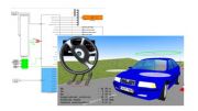 In the environment Matab/Simulink+Simmechanics have created a wide range of simulation models of cars, from the simplest to complex models: single-track model without longitudinal dynamics, single-track model with longitudinal dynamics, model with constant roll axis (with constant position of centres of roll axis), detailed model including detailed models of wheel suspension, springing mechanism, various types of constant velocity joints of drive axles, self-locking axle and inter-axle differentials, models of tyre-road contact, and models of tyres including transient properties. The models are created using the own vehicle subsystem libraries. In the environment Matab/Simulink+Simmechanics have created a wide range of simulation models of cars, from the simplest to complex models: single-track model without longitudinal dynamics, single-track model with longitudinal dynamics, model with constant roll axis (with constant position of centres of roll axis), detailed model including detailed models of wheel suspension, springing mechanism, various types of constant velocity joints of drive axles, self-locking axle and inter-axle differentials, models of tyre-road contact, and models of tyres including transient properties. The models are created using the own vehicle subsystem libraries.
Data Analysis
This is a system of procedures and user interface created in Matlab software to analyze data obtained from measurements on the car and/or from simulation calculations. Matlab can combine work in special user interface of Data Analysis module to perform standard tasks, and then use original Matlab environment to perform non-standard tasks. This ensures universality of the module.
Continued developed tools are used to analyze the driver’s driving style, his or her actions when driving, and handling characteristics of a car. This environment is also designed to analyze outputs from simulation calculations.
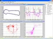 The module filters data, offers various views in several graphical windows, and supports synchronized movement of cursor in multiple windows. Moreover, it offers special data analyses with automatic search of special events (e.g. understeer/oversteer events, engine speed limiter on/off etc.) and presents the results in user-friendly graphical windows. As far as analyses of vehicle’s subcomponents are concerned, the software combines measured/simulated data with mathematical models and generates graphical windows providing information about the subcomponent state in the analyzed moment. In case of tests performed in compliance with ISO standards concerning vehicle dynamics, the module calculates quantities defined by the ISO and displays the graph of calculated quantities and characteristic values in a graphical window. The module filters data, offers various views in several graphical windows, and supports synchronized movement of cursor in multiple windows. Moreover, it offers special data analyses with automatic search of special events (e.g. understeer/oversteer events, engine speed limiter on/off etc.) and presents the results in user-friendly graphical windows. As far as analyses of vehicle’s subcomponents are concerned, the software combines measured/simulated data with mathematical models and generates graphical windows providing information about the subcomponent state in the analyzed moment. In case of tests performed in compliance with ISO standards concerning vehicle dynamics, the module calculates quantities defined by the ISO and displays the graph of calculated quantities and characteristic values in a graphical window.
On the basis of the measured lateral acceleration, speed and yaw rate, the software generates the circuit or track profile and automatically divides the track to straight sections and bends. Geodetic coordinates measured by GPS can be converted to local tangential orthogonal coordinate system. Trajectory tool integrated in this module can be used to analyze the track and create the model of trajectory.
The user can create comments that are firmly attached to either time points or locations on the track. Moreover, the program interface offers the possibility to create reports (by exporting the comments and analyses outputs to text file or Excel sheet). Close attention is paid to data visualization. The program displays data about the trajectory in a new and original way and thus provides well-arranged information for drivers and engineers who perform the tests.
Module author: Ing. Petr Porteš, Ph.D.
Characteristics
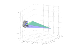
Trajectory
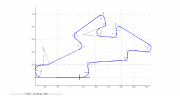 This module depicts the vehicle’s trajectory. The road is described by geometrical segments composed of straight sections (straight lines), circular arches and spirals. Due to this fact, the trajectory can be delineated using relatively small number of parameters. The trajectory is used to navigate the car during the simulation of close-loop maneuvers. Furthermore, this module is useful for planning of the trajectory, speeds, accelerations etc. during the test and describing the track by means of comments for drivers and testing engineers. The module offers an interactive interface for fast development of the trajectory using the records from GPS sensor. It is also possible to create new trajectory by polygon. The option to generate trajectories from maps will soon be available. This module depicts the vehicle’s trajectory. The road is described by geometrical segments composed of straight sections (straight lines), circular arches and spirals. Due to this fact, the trajectory can be delineated using relatively small number of parameters. The trajectory is used to navigate the car during the simulation of close-loop maneuvers. Furthermore, this module is useful for planning of the trajectory, speeds, accelerations etc. during the test and describing the track by means of comments for drivers and testing engineers. The module offers an interactive interface for fast development of the trajectory using the records from GPS sensor. It is also possible to create new trajectory by polygon. The option to generate trajectories from maps will soon be available.
Author of the software: Ing. Petr Porteš, Ph.D.
|


